53.27 - top level internal straight bracing connector
Table of Contents
Overview #
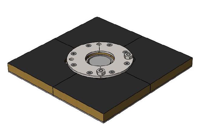
Assembled view #
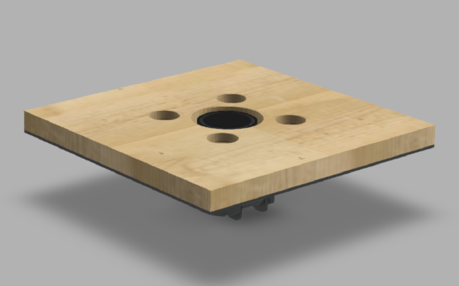
Exploded view #

Parts #
See order of use for 53.27 - top level internal straight bracing connector
Assembly steps #
Prerequisites #
- last level is installed
- central connector is installed
- sandwich panels are installed
Step 1 #

Insert 2 pcs. of 1.5 plywood washer into sandwich panel holes.
Step 2 #

Put 2 pcs. 99.91001 washer 1 in each hole of the sandwich panel and screw in with 2 pcs. of 99.91035 screw.
Step 3 #

Position 2 pcs. of 10.15 floor plate with countersunk holes as depicted in the image above.
Step 4 #

Fasten floor plates with 8 pcs. of 99.73 countersunk screw in designated holes for countersunk screws.
Step 5 #

Position 15.40 bracing bracket as depicted on the image above and fix with 2 pcs. of 99.91025 bolt from underneath.
Step 6 #

Tighten with 2 pcs. of 99.91008 hex nut.