53.10 - level 1 internal cross bracing connector
Table of Contents
Overview #
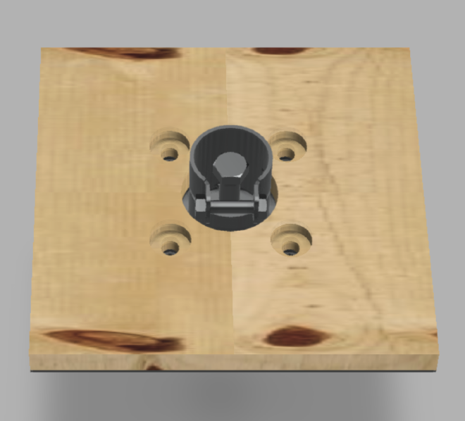
Assembled view #

Exploded view #
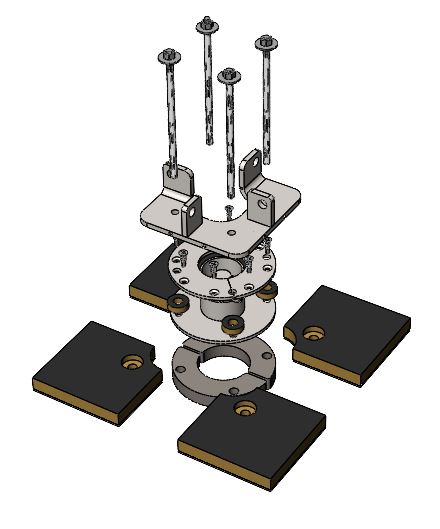
Parts #
See order of use for 53.10 - level 1 internal cross bracing connector
Assembly steps #
These are assembly instructions for adding fasteners to a connector adaptation. Before adding fasteners the following are prerequisites:
- the slab is level
- baseplate connector is staged per layout
- sandwich panels are staged
Step 1 #

Position 2 pcs. of 4.11 shim for baseplate connector in such a way that they ensure uniform levelness across all connectors on the first level.
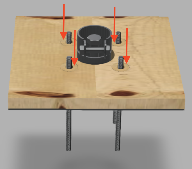
Step 2 #
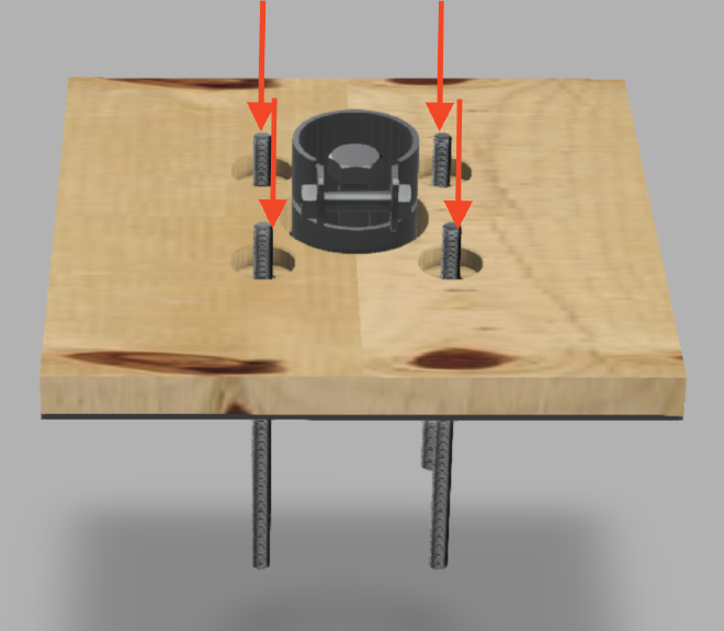
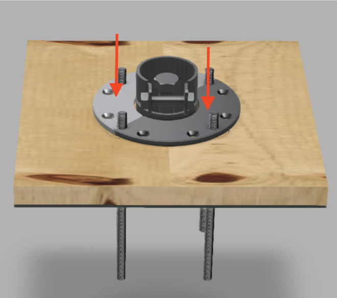
Drill holes at the designated points, then proceed to securely install 4 pcs. 99.15 anchor 3/8-16 in these holes.
Step 3 #
Insert 4 pcs. of 1.5 plywood washer into sandwich panel holes.
Step 4 #
Position 2 pcs. of 10.15 floor plate with countersunk holes as depicted in the picture above.
Step 5 #
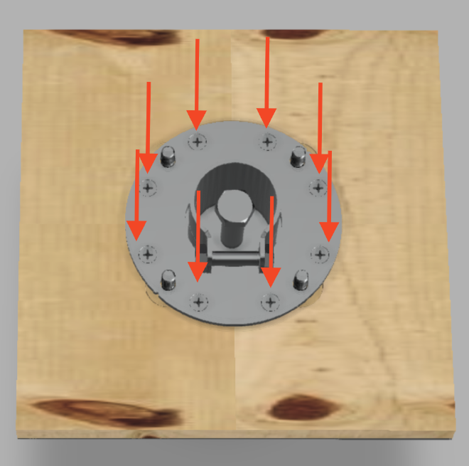
Fasten floor plates with 8 pcs. of 99.73 countersunk screw in designated holes for countersunk screws.
Step 6 #
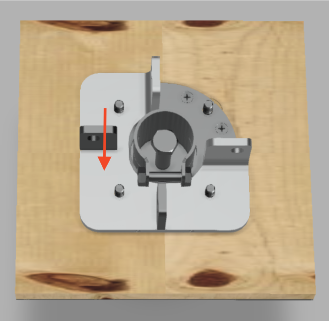
Position 15.56 cross bracing bracket as depicted on the image.
Step 7 #
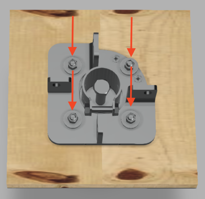
Add 4 pcs. of 99.91001 washer onto the screws and fasten with 4 pcs. of 99.13 hex nut.