53.11 - upper level perimeter straight bracing connector
Table of Contents
Overview #
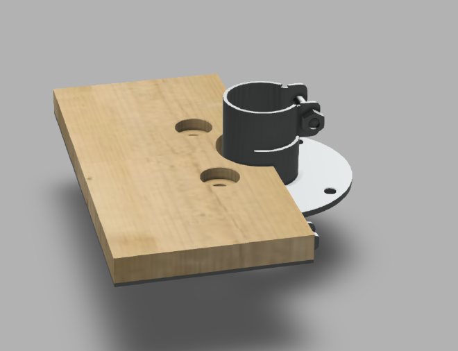
Assembled view #

Exploded view #

Parts #
See order of use for 53.11 - upper level perimeter straight bracing connector
Assembly steps #
Prerequisites #
- fL2 or higher is installed
- central connector is installed
- sandwich panels are installed
Step 1 #
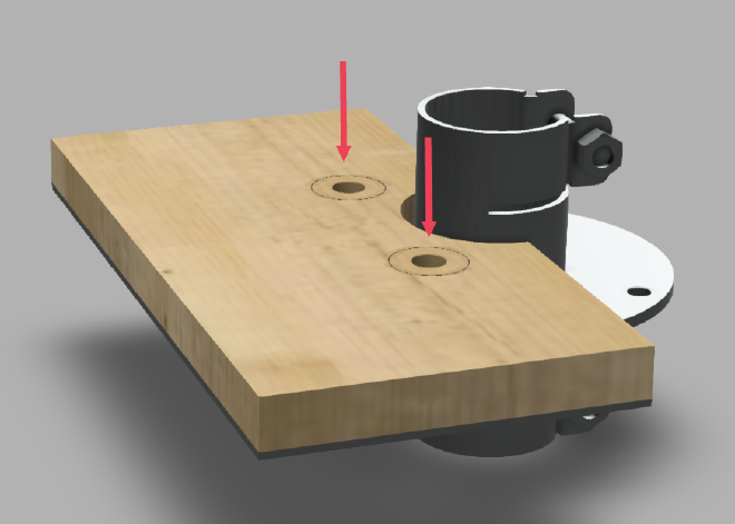
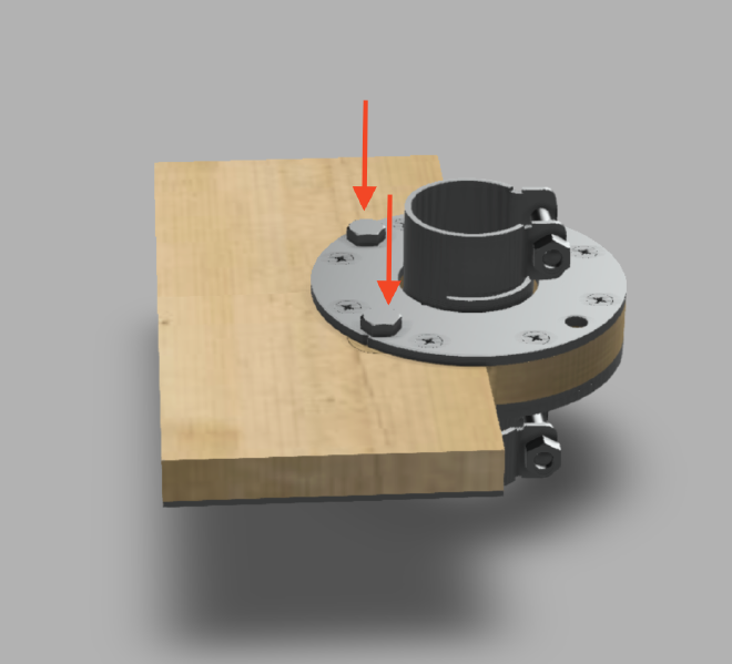
Insert 2 pcs. of 1.5 plywood washer into sandwich panel holes.
Step 2 #
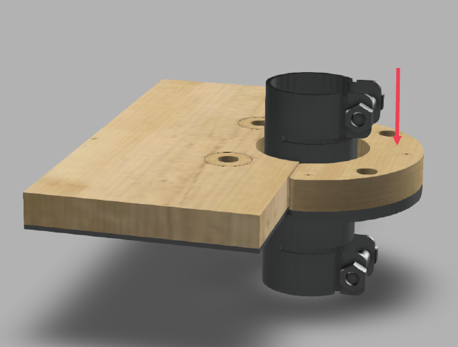
Position 3.4 spacer as depicted on the picture above.
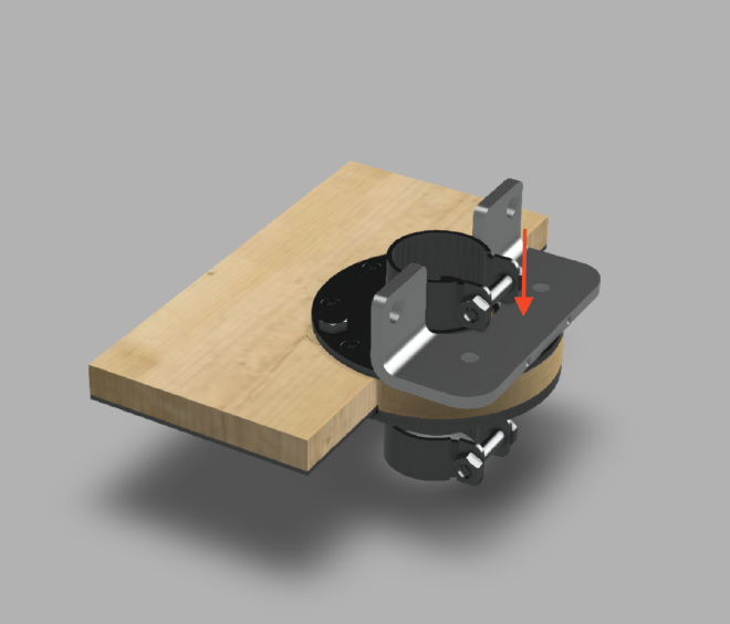
Step 3 #
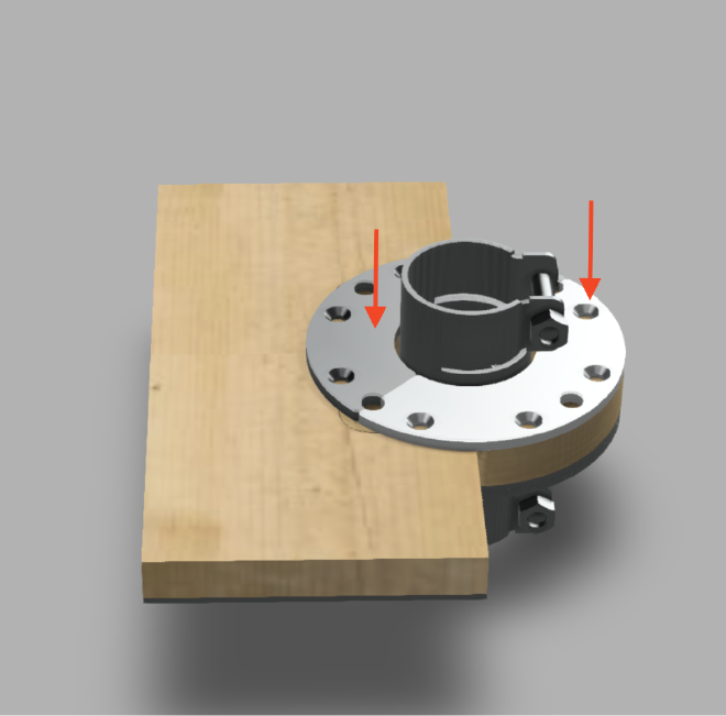
Position 2 pcs. of 10.15 floor plate with countersunk holes just as depicted in the picture above.
Step 4 #

Fasten floor plates with 8 pcs. of 99.73 countersunk screw in designated holes for countersunk screws.
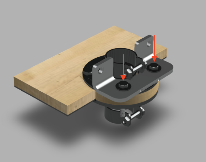
Step 5 #
Fasten floor plate with 2 pcs. of 99.91035 screw.
Note: do not tighten the screws before Step 8
Step 6 #
Position 15.40 bracing bracket as depicted on the image.
Step 7 #
Position 2 pcs. of 99.91001 washer onto the holes on the bracing bracket. Screw in 2 pcs. of 99.29 screw.
Step 8 #

Position 15.40 bracing bracket Bracket for bracing, edge (sheet metal) on the bottom of the connector as depicted on the image. Fasten with 2 pcs. of 99.91008 hex nut.