53.21 - upper level internal straight bracing connector
Table of Contents
Overview #
Assembled view #

Exploded view #

Parts #
See order of use for 53.21 - upper level internal straight bracing connector
Assembly steps #
Prerequisites #
- fL2 or higher is installed
- central connector is installed
- sandwich panels are installed

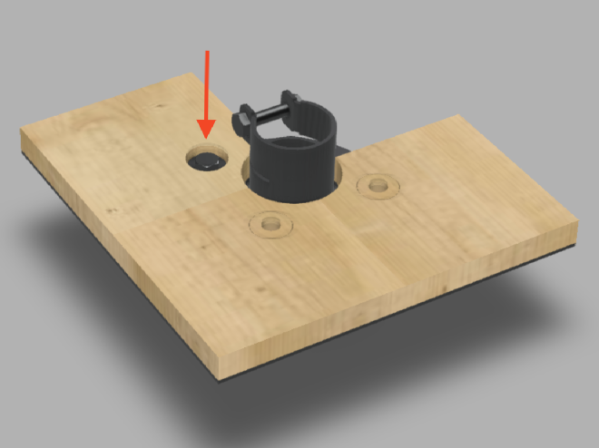
Step 1 #
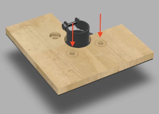
Insert 2 pcs. of 1.5 plywood washer into sandwich panel holes.
Step 2 #
Place 1 pcs. 99.91001 washer and fix with 3 pcs. 99.91035 screw.
Step 3 #

Position 2 pcs. of 10.15 floor plate with countersunk holes just as depicted in the picture above.
Step 4 #
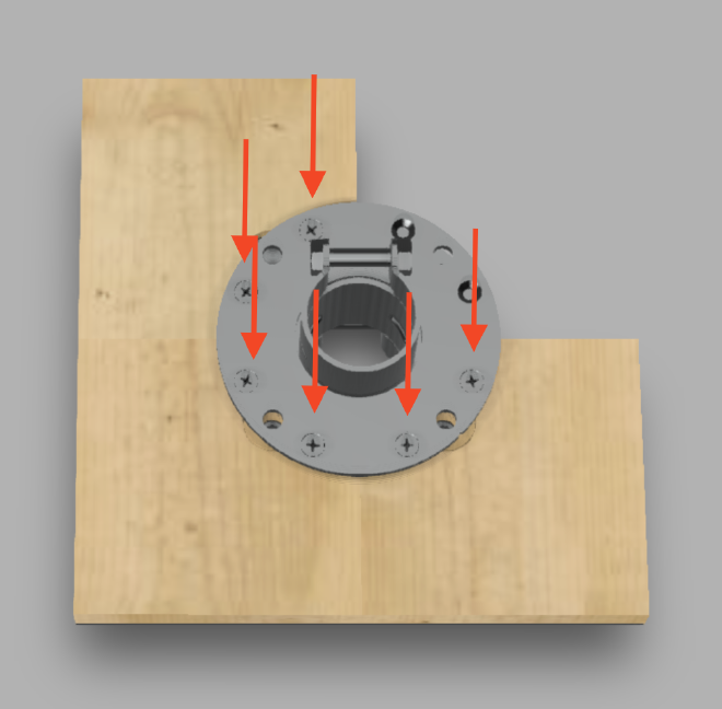
Fasten floor plates with 8 pcs. of 99.73 countersunk screw in designated holes for countersunk screws.
Step 5 #
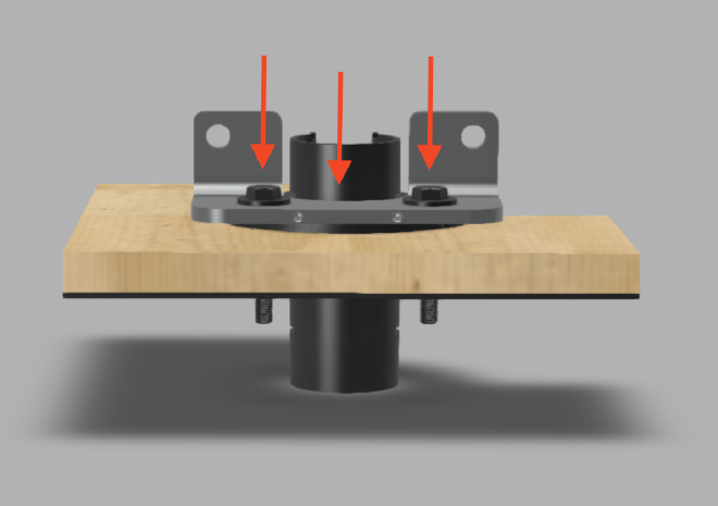
Position 15.40 bracing bracket, position 2 pcs. of 99.91001 washer onto the holes on the bracing bracket and screw in 2 pcs. of 99.29 screw.
Step 6 #
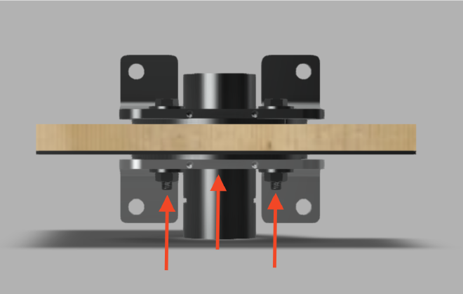
Position 15.40 bracing bracket on the bottom of the connector as depicted on the image, add 2 pcs. of 99.91001 washer onto the screws and fasten with 2 pcs. of 99.91008 hex nut.