53.4 - safety barrier for maintenance shaft with door for robot
Table of Contents
Overview #
This manual provides instructions for installing safety barrier for a maintenance shaft using mounting clamps on the floor and ceiling levels.
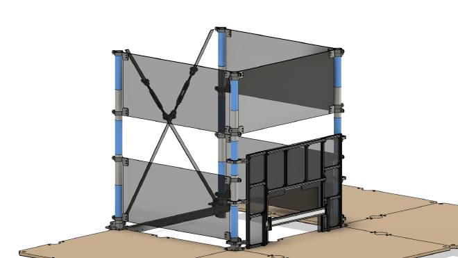
Parts #
See order of use for 53.4 - safety barrier for maintenance shaft with door for robot
Assembly steps #
Prerequisites #
- Level with maintenance shaft is installed
- Bracings are installed
- Robot doors are installed
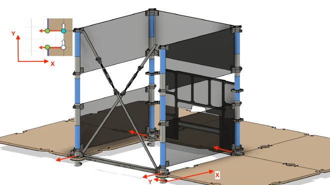
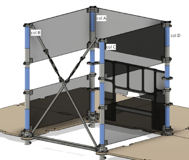
Step 1 #
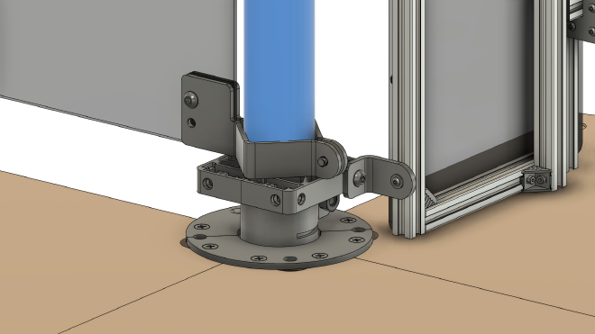
Mount 15.13 half clamp and 15.14 half clamp (assembly of 15.18 clamp) onto the bottom of Column A and fasten with 99.2217 screw. Refer to the clamp’s position in the images below for proper mounting.
Tighten just enough to ensure that clamp remains securely attached to the column. Ensure that the side of the clamp with threaded holes is oriented towards the center of Column B.
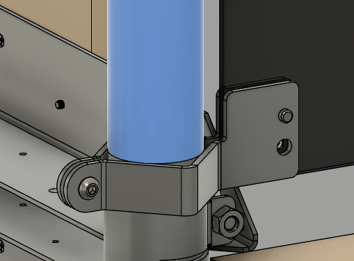
Step 2 #
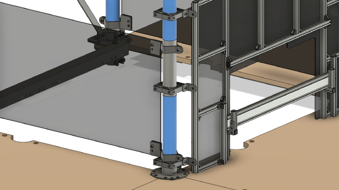
Mount the clamp onto the middle of Column A. Repeat the instructions from step 1. Ensure that the clamp is positioned as depicted in the image below.

Step 3 #
Proceed to repeat steps with Columns B, C and D.
Step 4 #
Repeat steps 1-3 for Columns A, B, C, D at the ceiling level.
Step 5 #
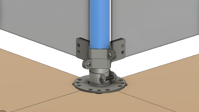
Mount additional clamps for safety panels onto Column A, so that an “angle” is formed. Now, the clamp with threaded holes must be oriented towards the center of Column D.
Step 6 #
Proceed to repeat step 5 with Column D. Ensure that the clamps with threaded holes is oriented towards the center of Column A.
Step 7 #
Ensure that clamps on opposite columns are positioned at the same level, so that the safety panel can be installed. If required, adjust the clamps on the column.
Step 8 #
Position the safety panel so that its holes align with the clamp’s threaded holes. Fasten with a 99.2217 screw.
Step 9 #
Repeat steps 7 and 8 to install the remaining safety panels.